Oilfield Wellhead Tool Double RAM Blowout Preventer 2fz18-70
UPET GROUP CO., LTD.- Manufacturing Process:Forging
- Surface Treatment:Galvanized
- Operation Pressure:Atmospheric Pressure
- Material:Cast Steel
- Warranty:1 Year
- Appplication:Oilfield
Base Info
- Model NO.:2fz18-70
- Colour:Customer Requirement
- Condition:New
- Transport Package:Container
- Specification:3 1,8",3 1,2",4 1,8",4 3,4",5",6",6 1,4′,6 1,2",6
- Trademark:UPET
- Origin:China
- HS Code:73061900
- Production Capacity:200000 PCS,Year
Description
Basic Info.
Model NO. 2fz18-70 Colour Customer Requirement Condition New Transport Package Container Specification 3 1/8",3 1/2",4 1/8",4 3/4",5",6",,6 1/4′,6 1/2",6 Trademark UPET Origin China HS Code 73061900 Production Capacity 200000 PCS/YearProduct Description
Quick DetailsPlace of Origin:Shandong, China
Model Number:2FZ18-70
Type:Bop
Machine Type:Drilling Tool
Certification:API
Material:alloy steel
Processing Type:Forging
Use:Well Drilling
Semi sealed working pressure:70 MPa
Whole sealed working pressure:70 MPa
Oil cylinder working pressure:8.4~10.5 MPa
Opening diameter:180 mm
Outline dimensions:2054*510*1081 mm
Supply Ability
Supply Ability:30 Set/Sets per Month
Packaging & Delivery
Packaging Details
Export packing, each packed in a wooden case, or as per customer's requests.
Port:Qingdao, Shanghai, Tianjin, etc
Lead Time :15 days
2FZ18-70 hydraulic blowout preventer
I. Overview
The blowout preventer is a key part of the well control device. It is mainly used for midway testing of drilling, oil production, oil testing, and downhole operations of new well perforation. It controls wellhead pressure during operations to effectively prevent blowout accidents and achieve safe construction. Putting an end to environmental pollution, installing a hydraulic blowout preventer can not only shorten the time for sealing the oil pipe, but also greatly improve work efficiency.
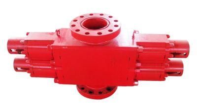
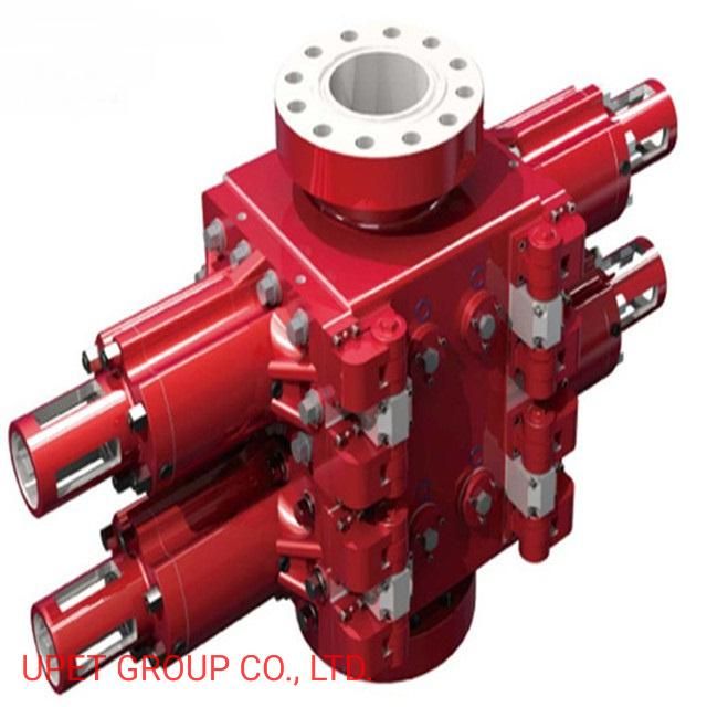
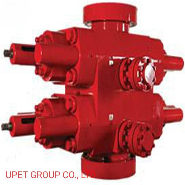
2. Introduction to product structure
The hydraulic blowout preventer is mainly composed of a shell, a side door pressure part, a hydraulic system device, and a sealing assembly.
The shell, side door pressure parts and connecting bolts of the blowout preventer are all forged from alloy steel. All metal parts are surface treated with nickel-phosphorus electroless plating, which has excellent anti-corrosion performance. The sluice chamber on the shell adopts an elliptical structure, which improves the force distribution of the shell and improves the safety performance of the shell. Wait until it is pushed to the well head, and the ram assembly can be replaced easily.
The hydraulic system consists of a remote control console, pipelines, hydraulic cylinder piston shafts, etc. The control system can be controlled by a single control or multiple controls according to customer needs. The equipment is advanced but must be operated by full-time personnel.
The hydraulic blowout preventer has reasonable design, compact structure, light weight, small size, convenient operation and maintenance, and is well received by users.
3. Main technical parameters
1. Model: 2FZ18-35
2. Maximum working pressure: 35MPa
3. The outer diameter of the upper and lower connecting flanges: φ480mm
4. Hydraulic cylinder diameter: φ130mm
5. Outer diameter of gasket ring groove: φ241.83mm
6. Pad ring number: BX156
7. Bolt: 12-M36×3
8. Number of rotations of the locking shaft: 14
9. Equipped with ram assembly: fully enclosed ram, 2 semi-enclosed ram
10. Overall dimensions (length × width × height): 1385×480×730mm
11. Machine weight: 960Kg
12. Diameter of sealed tubing: 73mm
4. working principle
4.1 Hydraulic BOP switch
The hydraulic blowout preventer closes the opening and closing on the main hydraulic console to control the pressure. The pressure enters the pipeline and then enters the hydraulic cylinder of the blowout preventer, thereby pushing the piston shaft (ram shaft) to make the left and right ram assembly, At the same time, it moves to the center of the wellhead to achieve the purpose of closing the well. When high-pressure oil enters the opening chamber of the left and right oil cylinders, the left and right ram assemblies simultaneously move away from the center of the wellhead to achieve the purpose of opening the well. The opening and closing of the gate is controlled by the reversing valve in the hydraulic control system. The opening and closing force of the gate is proportional to the force area of the piston and the hydraulic pressure acting on this area.
4.2 Sealing and characteristics of gate
When the blowout preventer closes the wellhead, there must be four sealing functions at the same time to achieve effective sealing. Namely: the top seal on the gate assembly is sealed with the upper part of the gate chamber of the shell; the seal between the front seal of the gate and the pipe string; the seal between the shell and the side door; the seal between the side door and the gate shaft; one missing No. The top seal is because the height of the ram chamber is smaller than the top seal on the assembly. The top seal is sealed by squeezing deformation. When there is pressure in the well, the upward well pressure can act as a sealing aid. The front seal is on the locking shaft Under the thrust, the rubber will deform and play a sealing role in contact with each other. The side door and the shell are sealed with an "O" type sealing ring. The side door and the gate shaft are sealed by a combination of YX type sealing ring and "O" type sealing ring.
When opening the wellhead, turn the locking shaft to the left and then turn it around to the right to make sure that there is a loose gap everywhere. The second is to make the top seal and the front seal have a larger space when entering the shell to prevent the rubber from being damaged by long-term compression.
5. precautions for on-site installation and use
5.1 Pay attention to the pressure rating, the size of the built-in ram should be installed according to the combination of blowout preventers required by the well control regulations.
5.2 When closing the BOP, first check whether the pipeline connected to the BOP is consistent with the BOP switch. The console can use a control pressure of 2-3 MPa to perform a switch test to remove the air in the oil pipe. The direction of movement is opposite to that of the console, and the connecting pipeline is reversed.
5.3 When the blowout preventer needs to close the well for a long time, lock the ram in the closed position when the ram is hydraulically closed. At this time, the hydraulic pressure can be released, but if the ram is opened, the manual lock shaft must be loosened by turning left. , Then use hydraulic pressure to open the gate, this is the only way to open.
5.4 When the pipe ram is closed during the test without a string in the well, the maximum hydraulic pressure cannot exceed 3MPa to avoid damage to the rubber core. When there is a pipe string in the well, it is strictly forbidden to close the fully enclosed ram.
5.5 There is at least one spare set of the installed ram at the well site. Once the installed ram is damaged, it can be replaced in time.
5.6 When the well is to be closed for a long time, the ram shall be locked with a locking device. Manual locking should be listed on the console to prevent misoperation.
5.7 Tighten the connecting bolts evenly and tighten them diagonally.
5.8 The use of the blowout preventer should be assigned a special person to be responsible for the implementation of responsibilities, and the user should have three understandings (understanding the working principle, understanding the performance, understanding the process; knowing the operation, maintenance, maintenance, and troubleshooting).
5.9 After entering the destination floor, the gate should be opened and closed once a day to check whether the switch is flexible and whether the manual locking is easy to use. The fully enclosed ram switch test should be done after each tripping. It is strictly forbidden to close the fully enclosed ram when there is a pipe string in the well.
5.10 It is not allowed to release the pressure by opening the gate to avoid damage to the rubber core. Each time you open the gate, check whether the manual locking device is unlocked. After opening, check whether the ram is in the fully open position (all return to the housing) to prevent the drilling tool from damaging the ram.
5.11 Pay attention to keep the hydraulic oil clean.
5.12 After the blowout preventer is used up, the ram should be in the fully open position for maintenance.
Company Information
UPET OILFIELD EQUIPMENTS CO.,LTD is one of the most well-known suppliers for the oilfield equipments in China, was established in 2000, and now has grown up to a star company which is not big but very strong in this field with our persistant effort step by step in the past years.Our products refer to the whole areas of oilfields, from a very small spare part to a very big complete rig system. Our main products are: pump spare parts, mud pumps&packages, DC/AC Motors, solid control equipments, power units, truck-mounted rigs, workover rigs, land rigs, drilling pipes and drilling tools etc. All of our products are manufactured according to the API Standard, and we are authorized to use API monogram.
Our products have been exported to 15 countries& areas around the world, 80% of our exsisting customers have done the business with us by more than 5 times, no one-off customer. We will continue to expand our range, and win more customers' trust with our better and better performance.
We welcome the win-win cooperation relationship with the partners from any places in the world, each customer is our god and helper. Warmly welcome you to come to China and visit us!
With us, you will save money, time, trouble, and most important point is that you can sleep better.